

6. Contact Time between the Oil and the Bleaching Clay: Bleaching process in edible Oil,
Bleaching process in edible Oil.
When the absorbent comes into contact with the Oil, it does not immediately absorb the impurities. Therefore, the process allows the oil absorbent to stay in the bleacher vessel for a specific period of time.
The typical contact time is 30–45 minutes. In some instances, contact time as low as 20 minutes might be sufficient.
Contact time:
However, the contact time is too short, and impurity absorption does not reach completion.
The process of adsorption is also compounded by the fact that there are different impurities in the
Oil with different degrees of affinity for the adsorbent.
Therefore, more of the impurity with the most excellent affinity for the adsorbent would be adsorbed initially, and then some.
Additional time is needed for the others to be absorbed.
A longer contact time is not necessary in the bleaching process of edible Oil.
Disadvantages:
Bleaching process in edible Oil. A very long contact time may have the following disadvantages:
The acidic clay may react more with the Oil and especially with the chlorophylls, and cause their breakdown.
There may be a higher loss of the natural antioxidants in the Oil.
There may be formation of dimmers or polymers in the Oil.
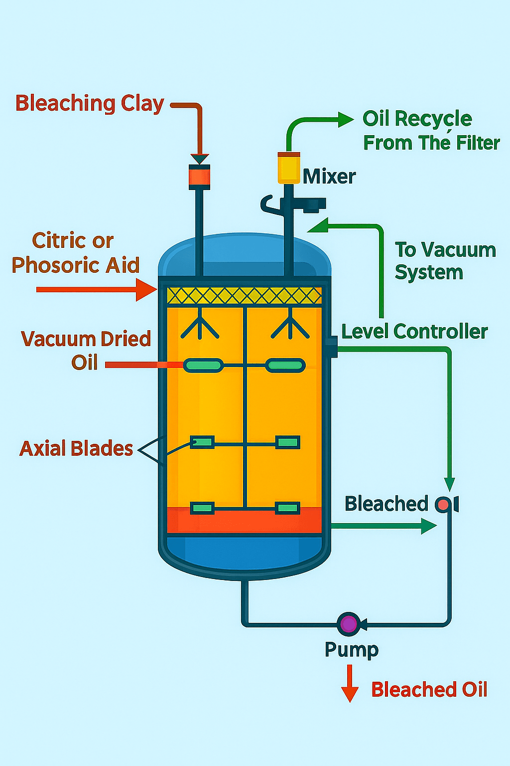
Level controller modulates:
Bleaching process in edible Oil.
Moreover, the re-circulating keeps the loop oil level in the bleacher, while a level sensor detects the set point and sends the information to the controller for adjustment.
The level controller modulates the 3-way control valve to return part of the Oil to the bleacher and to send part to the filter.
During start-up, the operator also recycles from the filter bag into the bleacher.
Thus, the Oil and the bleaching clay get the required contact time for bleaching.
7. Addition of Phosphoric Acid or Citric Acid: Bleaching process in edible Oil.
Furthermore, the operator adds a small amount of Phosphoric or citric acid directly into the bleacher. The typical dose is 50–300 PPM, depending on the level of trace impurities in the Oil.
The purpose of acid addition is to hydrolyse part of the soap in the Oil and improve the efficiency of scavenging the trace metals from the Oil by the clay.
The oil feed and the acid streams pass through a static mixer or a high shear mixer before entering the bleacher.
Acid fails to dissolve in the Oil. However, the vigorous mixing by the mechanical mixer allows intimate mixing between the acid and the Oil.
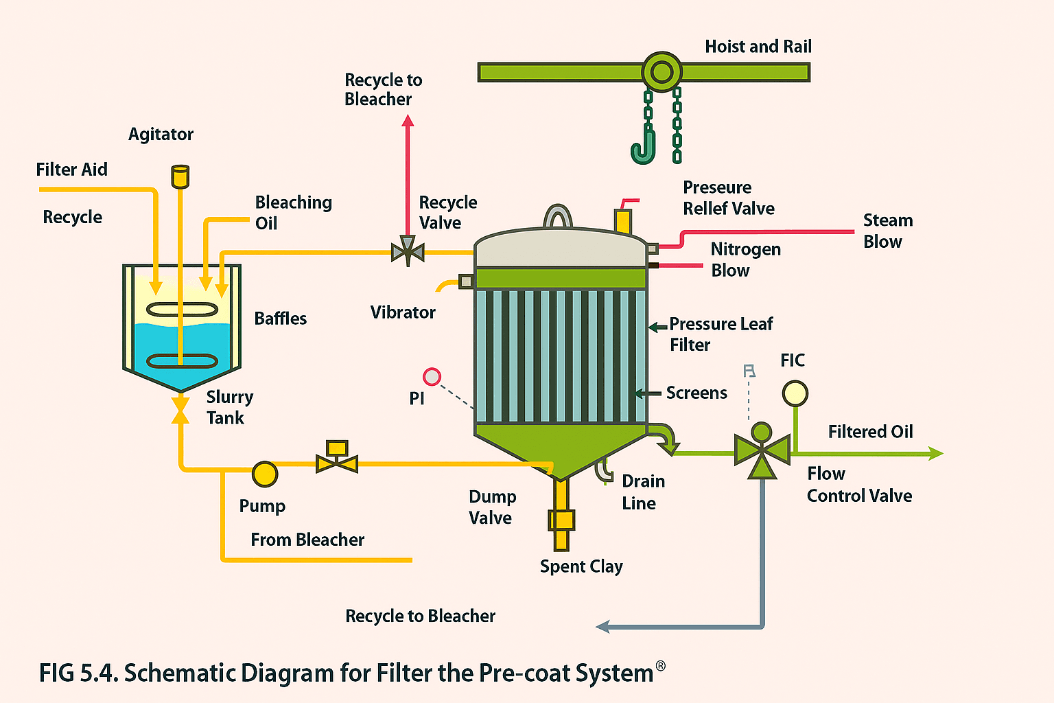
8. Filter Pre-Coat: Bleaching process in edible Oil
This is a significant step in filtering bleached Oil, whether from the dry or wet bleaching process.
The suspended bleaching clay in the bleached Oil tends to prematurely blind the filter screens and reduce oil flow through the filter.
Therefore, it is necessary because the filter cycle time can be significantly reduced in the absence of proper pre-coat on the pressure leaf filter screens.
Filter pre-coating is a simple operation, but it does not yield the desired results if not done correctly.
Pre-Coating Operation:
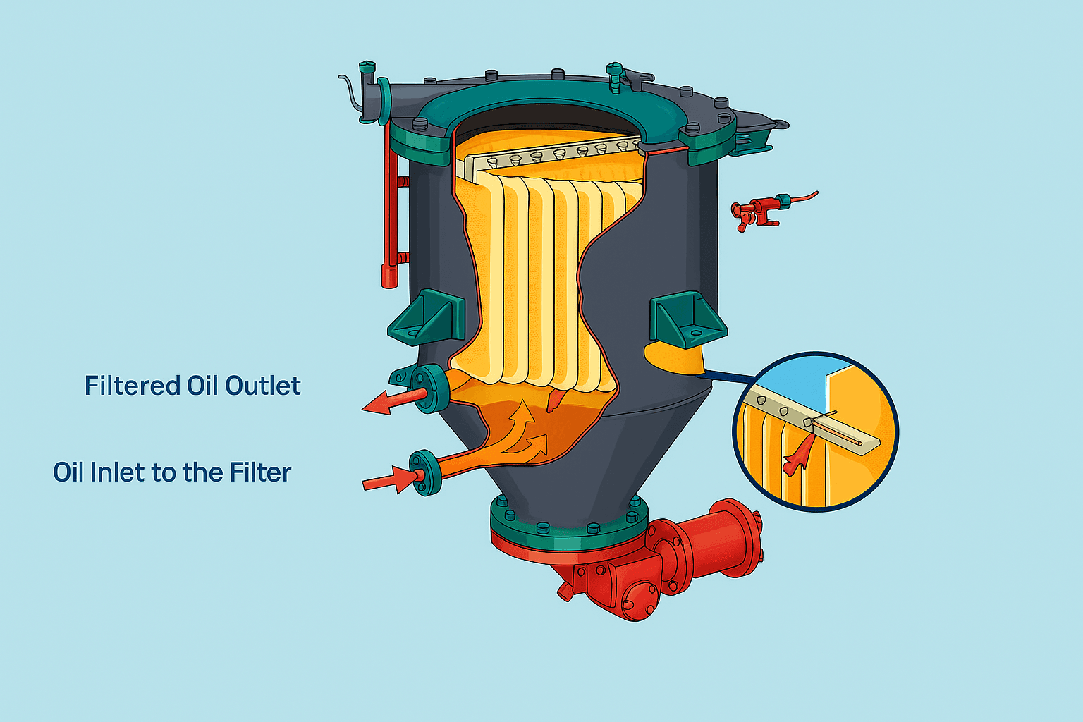
- First of all, Oil with the bleaching clay enters the filter at the bottom.
2. Meanwhile, the Oil follows upward along the surface of the filter screen.
3. Then, after, filtered oil flows across the filter screens and falls to a manifold through which the filtered Oil passes forward.
The step-by-step procedure for filter pre-coating is outlined below:
1. After that, filtered bleached Oil at a temperature of 100 –120°C (212– 230°F) is pumped into the slurry tank.
The volume of Oil in the slurry tank must match the total volume of the filter, piping, and accessories, plus 25–30% extra.
2. Diatomaceous earth (filter aid) is added to the Oil in the slurry tank. The amount of filter aid added is 0.1–0.2% of the Oil in the slurry tank.
Filter Aid dispersion:
3. Then, after, the filter aid is dispersed into the Oil with the help of a vertical mixer operating on medium speed (60 RPM). There are 3 to 4 baffles in the tank to avoid vortex formation.
Moreover, using a high-speed agitator is not recommended, as it can physically break down the filter aid.
Agitation in the slurry tank:
4. Agitation in the slurry tank is continued for at least 10 –15 minutes or longer to disperse the filter aid into the Oil fully.
5. Next, the operator pumps the slurry into the filter. The pump capacity should be twice the filtration rate of the bleaching.
For example, for 30,000 pounds per hour production (67 gallons per minute, GPM) of bleached oil production, the slurry tank pump capacity should be 135 GPM.
6. The slurry enters the filter at the bottom and moves up in a path parallel to the screen surface.
Flow indicator controller (FIC):
7. Consequently, as soon as the pump starts, the recycle valve opens. Simultaneously, the oil outlet valve opens.
8. Moreover, the flow indicator controller (FIC) positioned at the oil outlet line sets the desired production rate for bleaching.
9. The Oil coming out of the outlet line from the filter is recycled back into the slurry tank until the Oil is clear.
10. The Oil is also returned to the slurry tank through the recycle valve, which is fully open.
11. The differential pressure sensor measures the pressure drop across the filter, and it is displayed on the differential pressure indicator (PI).
12. At the start of pre-coat, there is no differential pressure across the filter screens, as indicated by the PI.
Automatic vibration mode:
13. After re-circulating the Oil through the filter for one minute, the filter screens go into automatic vibration mode for one minute.
The purpose of this step is to loosen up any accumulated material in the screen.
14. The Oil coming out of the filter through the oil outlet line is checked for clarity via filter test.
15. Pre-coating is complete when the Oil is clear, as determined by the filter test.
8. Filtering Bleached Oil:
1. At this stage, the pump actively transfers Oil from the bleacher into the filter.
2. Oil recycles to the bleacher through the recycle line as well as through the oil outlet line, and the recycle process is continued until the Oil is found clear by the filter test.
3. Then, after, a filter test can be done manually, or the oil clarity can be determined with the help of a clarity meter.
Recycling:
4. After that, once the Oil looks clear, you stop recycling from the outlet line and send the Oil forward.
5. The 3-way control valve then opens to send the Oil forward to a cooler or to the following processing step.
6. Then, after the filtration process stops automatically at a predetermined time, ensure that the dirt load capacity in the filter is not exceeded.
At this point, the following sequences of events occur:
This is to avoid bridging and damage to the filter screen. At this point, the following sequences of events occur:
The filter blow cycle (using nitrogen) begins, and the clean Oil goes out through the oil outlet line.
The recycle valve closes.
The oil feed pump stops.
The valve on the oil feed line closes.
The flapper valve on the drain line opens, allowing the oil slurry from the bottom of the filter to flow to a scavenger filter.
Flapper valve:
As soon as the oil flow stops, the flapper valve closes, the steam blow cycle starts, and the nitrogen blow stops.
Steam dries the cake. The steam blows come out of the oil outlet line. The steam condensates, and the residual Oil from the filter screens go into a slop tank.
Furthermore, the operator recovers the Oil from the slop tank and usually sends it to acidulation.
Steam blow stops after 5 –10 minutes.
Vibrator
7. Immediately after the steam blow, the system activates the vibrator to discharge the material.
Cake from the screen surface.
8. The dump valve opens and allows the dry cake discharge to drop into a receptacle under the filter.
Spent earth:
9. Afterwards, the worker sends the spent earth to one of the following three steps.
To a heat recovery system where the energy from burning the absorbed Oil is recovered and used in the process.
Oil recovery:
The bleaching process in edible Oil is an oil recovery system in which some of the Oil is recovered via hot-water treatment of the bleaching clay, along with caustic.
Moreover, the clay absorbs the Oil and converts it into soap.
The soapy water is sent to acidulation. The water from the clay is drained and then sent to a landfill.
Sprayed with water and then sent directly to a landfill, where there are no environmental regulations against it.
Scrapers:
10. Therefore, the operator must scrap the screen when the cake discharge is poor.
11. The screen bundle is lifted and scraped gently using scrapers that do not have sharp surfaces, because that would damage the screen.
9. Filtering Area/Oil Flow Rate:
Therefore, you must choose the appropriate filter size to match the production rate.
Typically, designers create screen filters to handle an oil flow rate of 0.1-0.2 US gallons per square foot of filter area per minute.
This means for a production rate of 150 U.S. gallons per minute, the filter surface should be at least 750 square feet.
10. Filter Screen Spacing:
For the bleaching process, the filter spacing is 6 inches for chemically refined Oil. The recommended spacing is 5 inches for physical refining, where the crude Oil is bleached.

Comments are closed.